
Download
PDF document for download:
Introduction
The breakdown voltage in data sheets indicates to the engineer the voltage at which an insulation material fails. It is tacitly assumed that this value is only valid in "new condition".
A voltage rise of 500V/sec is usually used to test this breakdown through the insulation material. The breakdown voltage (IEC 60243 ) is then standardized to the thickness as e.g. kV/mm.
However, this value decreases more and more over the course of its service life. A large number of factors are involved in negatively influencing the insulation capacity of a material. Therefore, depending on the application, it is not enough to consider the individual influencing factors. Instead, the sum of all stresses in a specific case must be taken into account in terms of their effects.
In the following, we will try to give you an impression of the most common types of load to look out for:
Temperature
Generally speaking, the higher the temperature, the more corrosive and oxidative influences of the ambient air become effective. Or, to put it more generally, the speed of ageing increases as the temperature rises, with most processes following the so-called Arrhenius curve.As a rule of thumb in electronics, the service life is halved for every 10°C increase in temperature.
As a rule of thumb in electronics, the service life is halved for every 10°C increase in temperature.
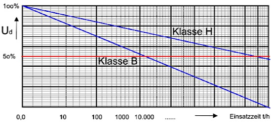
Insulation materials are divided into thermal classes (e.g. B=130°C, F=155°C, H=180°C) by IEC 60085 (Electrical insulation, thermal evaluation and designation). These classes indicate the continuous operating temperature at which the insulation materials still have, for example, 50% of the breakdown voltage they had when new after 20,000 hours.
To put it another way, this means that a material has lost half of its protective function against electric shock after less than two and a half years of use at the maximum permitted temperature. And this is due to thermal ageing alone.
So if you want to achieve a longer service life at a given operating temperature, you use an insulation material of a higher thermal class. The usual end-of-life criterion of "halved breakdown voltage" is achieved much later in this way.
With regard to the maximum heat that can occur, heat accumulation within windings, current density increase at outlets, maximum possible ambient temperature and any occasional malfunctions should also be taken into account.
Materials such as molding compounds (e.g. coil carriers), paints, impregnating agents and potting compounds that are used as insulation can become brittle, shrink or develop stress cracks due to heat. Surface insulation materials (e.g. NMN, DMD, etc.) can delaminate, where partial discharges can occur due to the epsilonr jump, similar to voids in potting compounds. In addition, weathering together with heat causes these materials to fail earlier.
Voltage (stress, partial discharge)
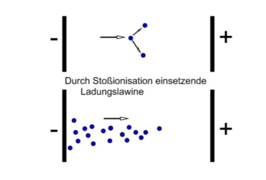
Corona discharge occurs on surfaces from 400V (sliding discharges, streamers). The resulting field strength accelerates free electrons to such an extent that they eject other charge carriers from their stable position. An avalanche of charge carriers develops, which then leads to a partial discharge (corona or sliding discharge).
These pulses cause insulation systems to age in a different way than under conventional, mains frequency AC voltage:
- Partial discharges destroy the insulation due to aggressive degradation products, UV radiation and ozone
- Formation of guide paths on the surface of the insulation
- Electromechanical fatigue due to current pulses
- Dielectric heating due to the high-frequency components of the voltage pulses
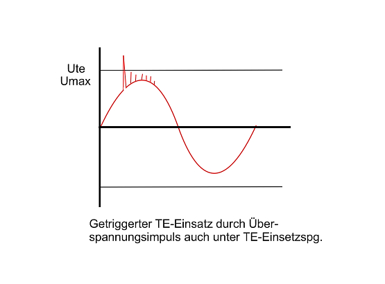
Even if the nominal voltage is below the PD inception voltage, such superimposed pulses (transients) can ignite partial discharges. The temperature, humidity, pulse shape, polarity and repetition rate have a significant influence on the degradation rate of the materials.
A sufficient distance from the PD extinction voltage is therefore always advisable. This is achieved - in addition to design measures (distance) - by using sufficiently voltage-resistant, i.e. "thick" insulation.
However, this contradicts the requirement for as little insulation material as possible within transformers and generators. This is because only the "iron" and copper components in a transformer are electrically effective. In addition, the capacitive and inductive coupling situation changes significantly.
If the risk of partial discharges cannot be ruled out, materials that are particularly resistant to PD are used. These include all inorganic insulating materials such as glass, ceramics or the natural material mica. They are not damaged by corona discharges. Increased corona resistance in surface insulating materials is achieved, for example, by inserting fine mica flakes. This significantly improves the corona resistance of high-voltage machines (generators, motors). Of course, this also applies to the insulation structure of motors that are operated on frequency converters (inverters, converters).
In large medium and high-voltage systems (motors, generators, distribution transformers), semiconducting materials can be used to avoid this glow discharge as far as possible. In this way, the electric field is shaped to such an extent that no dangerous field line concentrations can occur.
This concentration of field lines at edges and tips (e.g. the edges of insulated flat copper strips) places a much greater load on insulation materials and the insulation path through air than a homogeneous, flat E-field.
For smaller sizes and where PD discharges cannot be completely avoided, the use of Kapton® CRC or fluoropolymers such as FEP is recommended. The PD resistance of Kapton® CRC is drastically increased by adding inorganic materials to the polymer mass. Fluoropolymers are characterized by their low chemical reactivity and low r, but have other disadvantages (ductility, cold flow).
Difference in service life between Kapton HN and Kapton CR under partial discharge load (source: DuPont)
Potting compounds are a common means of preventing surface discharges (corona, sliding discharges). By coating all sides with polyurethane or epoxy resin, as a rule, epsilonr jumps are reduced and discharges through the air are prevented. Such potting compounds do not inherently have any particular partial discharge resistance, but allow any desired layer structure to achieve a high nominal dielectric strength. However, the decisive factor when using potting compounds in high-voltage applications is the absence of bubbles and blowholes, which is achieved by the vacuum potting process adapted to the individual case (if necessary with subsequent pressurization to improve impregnation).
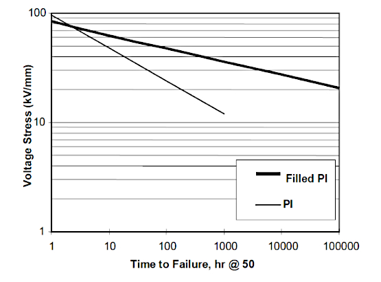
As with the observations on the influence of temperature, the use of a higher-quality material (e.g. a Class F material instead of Class B, Kapton® CRC instead of Kapton® HN or 50μm instead of 25μm film thickness) significantly postpones the time of destruction. Even when PD (partial discharge) occurs, the dielectric strength is maintained significantly longer compared to standard products.
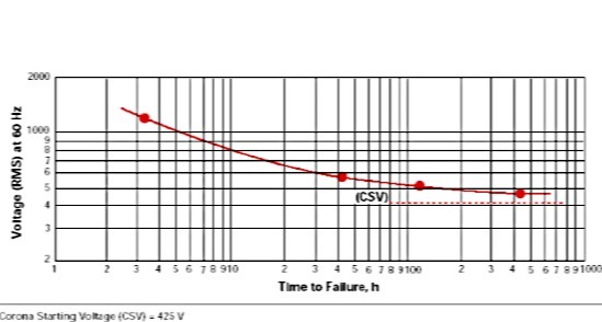
Duration until Kapton reaches the PD insertion stress under stress (source: DuPont)
IEC 60343 (Recommended test methods for determining the relative resistance of insulating materials to breakdown due to surface partial discharge; similar but not equal to ASTM 2275) describes an accelerated method from which the time to failure at a lower voltage load can then be extrapolated. Another important document on the subject is DIN IEC/TS 61934 (Electrical measurement of partial discharges (PD) with repetitive voltage pulses with short rise times).
Conclusion: Despite improved insulation materials, avoiding partial discharges in the insulation system remains the top priority when designing electrical equipment. The UV light, aggressive decomposition products and reactive ozone generated by such corona discharges generally affect the surrounding materials and not just the insulation material directly affected. It is also important to note that the dielectric strength of air is usually significantly lower than that of insulation materials.
Note1: measuring the level of PD in an electrical component is a common method of production monitoring today.
Note2: Positive or negative DC voltage stresses insulation materials in different ways. There are no losses due to the alternating field. However, partial discharges can still occur. Material migration can also occur.
Note3: The IEC 60505 standard (evaluation and marking of electrical insulation systems) attempts a comprehensive consideration of the aging behavior of complex insulation systems
Frequency
Many basic "electrical" standards normally measure with sinusoidal voltage at 50/60Hz (IEC 60243, Dielectric strength of insulating materials - Test methods). However, modern switching power supplies operate at significantly higher frequencies. This increases the stress on the insulating material.
Excursus: The electrical quantity "voltage" makes a statement about the force required to move a unit of charge. This "work" is increasingly applied to the insulating material as the alternating frequency increases. Non-polar materials such as ceramics or glass are less affected by this. However, organic insulation materials such as PE, PA, EP, PUR, PP, PET, PA, PI etc. are more or less polar.
The complex polymer chains form dipoles that try to align themselves with the external electric field. This results in mechanical stress and "frictional heat" within the material. The result is reduced dielectric strength.
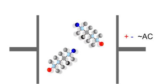
Re-polarization losses in insulation materials (source: CMC)
In high-frequency welding, these polarity reversal losses in the material are even used to melt the plastic (dipole-type plastics such as PVC, PA and acetates; high dielectric losses). Roughly speaking, the higher the applied electric field and the higher the frequency, the more thermal energy is transferred into the material.
What is desirable in welding is harmful for an insulation material in continuous use. This is because this "internal" heating often goes unnoticed when considering ageing and is not reflected in the usual standard measurements (e.g. UL 746).
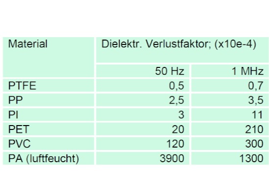
Overview of some insulating materials and their losses in the alternating electric field related to two different operating frequencies
Frequency converters and switched-mode power supplies now place more stress on insulation than in the past, because motor control systems or computer power supplies, for example, use pulse-width-controlled voltages in the range of 30 kHz and more.
The resulting harmonics have frequencies far above the operating frequency and peak voltages far above the operating voltage occur, e.g. due to resonances and inductive or capacitive coupling.
The high switching speeds dU/dt of modern MOS-FET transistors (SiC, GaN) place considerable stress on the insulation materials used (P= U² C tan (T) ≙ power loss in the material). In addition, wave reflection, standing waves and feedback from the powered device can cause further stress on the insulation. The load is also increased by capacitive coupling, e.g. from phase to earth or phase to phase.
The following diagram shows the relationship between high frequencies and the decrease in dielectric strength as a result of increasing electrical stress, using a polyester film as an example:
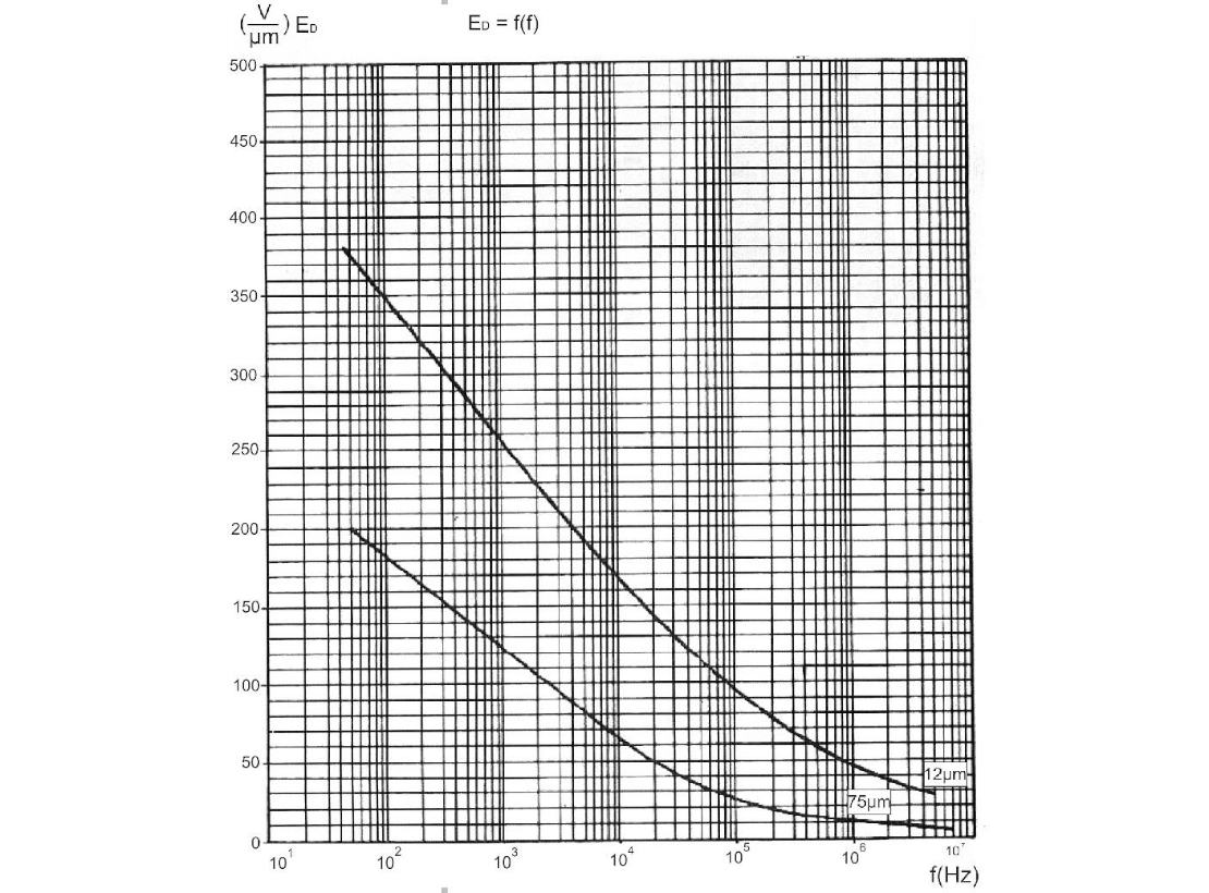
Dependence of breakdown voltage on frequency (source: Hoechst)
In many data sheets, the breakdown voltage for electrical insulating materials is specified in relation to a working frequency of 50/60 Hz sinusoidal current (IEC 60243, Dielectric strength of insulating materials). However, as shown in the diagram, many of the standard insulating films react at higher frequencies with a significantly reduced dielectric strength.
With many insulation materials, a significantly reduced dielectric strength occurs at greatly increased alternating frequencies (>>100 kHz; steep edges dU/dt with pulse width modulation PWM also generate such frequencies). The reason for this is the fact that surface and space charge zones form on and in the material at sufficiently high voltages. At high frequencies, these can no longer dissipate until the AC voltage crosses zero. The remaining charges are stored and lead to an increase in the field.
If the field strength is sufficiently high due to the additional space charges, partial discharges occur. The destruction of the surface of the polymer insulator begins. The resulting deposits on the surface of the insulator lead to leakage currents, which further shorten the time to breakdown.
The IEC 62631-2-2:2022 standard therefore deals with the "Dielectric and resistive properties of solid electrical insulating materials" at frequencies from 1 MHz to 300 MHz for good reason. In addition to the higher switching frequencies, the high-energy harmonics are also covered (modern SiC MOSFETs can achieve switching frequencies in PWM mode of >> 1 MHz at switching voltages >> 1,000 V).
It is particularly critical that this effect can occur unexpectedly strongly even with a high DC voltage if a high-frequency AC voltage is superimposed. As described above, the remaining space charges increase the E-field strength beyond the supposed peak value of the voltage (DC plus ripple), so that the breakdown voltage of the insulator can be exceeded.
Important note: The standardized breakdown voltage does not increase proportionally with increasing material thickness. Rather, the breakdown voltage in V/μm is significantly lower with greater thickness due to the losses within the material!
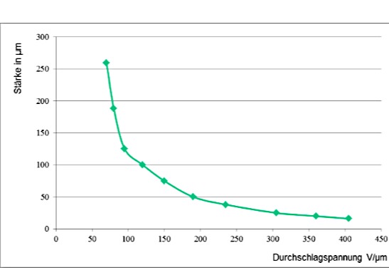
Breakdown voltage versus material thickness for polyester film (source: CMC)
Conclusion: In addition to ageing due to temperature and the weakening of the material due to partial discharges, the frequency also has a significant influence on the design of an electrical device. As a rough rule of thumb, the dielectric strength of a polymer insulator of a certain thickness drops to the value of an equivalent air gap (clearance) from around 500 MHz.
Behavior in the event of pollution (environment)
If the surfaces of insulating materials are contaminated by moisture and dust, conductive paths are slowly but surely created when sliding discharges occur. These consist of carbonized remnants of the contamination and the destroyed insulating material. These conductive paths usually spread further and further in branches (treeing) and can ultimately lead to failure of the insulation. Similar phenomena occur within castings or molded parts, especially if they are brittle and cracked.
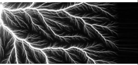
Formation of a conductive path (electrical treeing) on or in insulation materials (source: CMC)
A key aspect here is the possible absorption of water by the insulating material, as this also accelerates destruction within the material (treeing). Certain products that are manufactured using polycondensation (e.g. polyester films, polyimides) can even be damaged relatively quickly by hydrolysis in the presence of moisture and temperatures above 85°C (e.g. laminated flat cables made of polyester in car side doors).
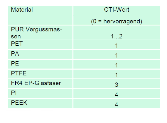
The so-called CTI value or tracking resistance is used to indicate how easily a material tends to form conductive paths on the surface. The Comparative Tracking Index (CTI) in accordance with DIN EN 60112 (method for determining the test number and the comparative tracking index of solid, insulating materials; also UL 746 B) is measured as follows: Two electrodes are placed on the surface to be measured. A conductive salt solution is dripped between them and a voltage is applied. The voltage at which the surface of the material is eroded by flashovers then classifies it into one of 4 insulation material groups (IEC 60664).
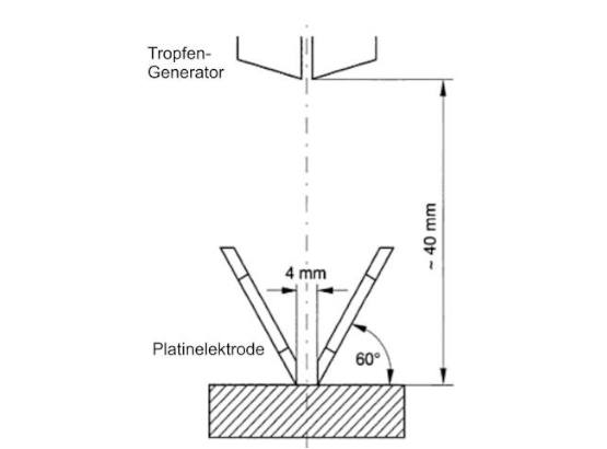
Measurement of the CTI value on insulating materials (source: UL 746 B)
This particular combination of sliding discharge and contaminated surface leads to the destruction of the insulation material even faster than dry partial discharges. Increased distances are therefore prescribed, particularly for electrical equipment used outdoors where there is a risk of condensation (see EN 61558, Safety of transformers, power supply units, chokes and similar).
Constructive measures
There are several ways to ensure electrical safety even after thousands of operating hours. Increasing the clearances and creepage distances provides essential protection to ensure that nothing happens even with aged insulation materials due to the reduced dielectric strength. The required clearance and creepage distance is a function of the tracking resistance, degree of contamination, overvoltage category, frequency and area of application (household, industry, medicine).

Increasing clearance and creepage distances to prevent age-related breakdown (source: EN 61558)
The design can also be made more fault-tolerant, for example. The use of an insulation material of the next higher insulation or CTI class is often relatively simple and yet highly effective. The time to failure can normally be at least doubled in this way.
In addition, the quality of the materials used also determines the performance over the entire service life. Particularly in the case of multilayer materials, failures due to lamination errors can lead to failures or contaminated resins can contribute to a premature weakening of the dielectric strength.
Finally, the mechanical loads during processing (e.g. tensile load on enameled wire) and the possible pre-damage caused by test procedures for production testing (e.g. high-voltage test) are of course also decisive for the service life.
Other possible causes
Temperature, voltage stress, unfavorable material properties and partial discharges are certainly the most effective degradation mechanisms for polymers. However, there are other factors that can play a role depending on the place of use.
Almost all plastics are damaged by radiation (UV light, radioactivity). The high-energy radiation destroys the polymer chains and leads to lower mechanical strength, for example.
Something similar can happen with special plastics such as polyester, polyamide and polyimide through a process known as hydrolysis. With sufficiently high energy (e.g. water vapor at >85°C), the bonds in the polymer chain are broken by the dipole H2O. Tests on 50μm thick polyester film have shown that the mechanical strength is largely lost after just 1,500 hours at 85°C / 85% relH. The film breaks during a buckling test (DIN EN 61234, test method for hydrolysis resistance of electrical insulating materials).
When assessing insulating materials, the so-called "motorette test" (e.g. UL 1446) also takes into account their resistance to mechanical vibration, as occurs in rotating machines. This tests whether the plastic tends to erode under the effect of friction and thus reduce its dielectric strength.
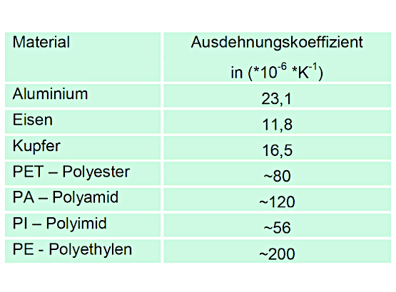
Constant temperature changes (e.g. only intermittent operation) are particularly stressful for composites made of insulation material and core material or enameled wires. The expansion coefficients of plastics are usually far higher than those of metals. This "mismatch" in expansion and contraction can lead to stress cracks, especially in potted systems.
Finally, the chemical compatibility of all materials used in an insulation system (UL 1446, IEC 61858 and IEC 61857) also plays a role in the ageing resistance of the individual components. In long-term ageing tests or shortened tests (sealed tube test), the interaction of all insulation materials is tested during ageing. Incompatibilities are indicated by a reduced dielectric strength.
Influence maximum stake height
Normally, the limit values specified in the various standards for insulation materials apply to a maximum operating altitude of 2,000 meters. The reason for this is the noticeable decrease in the insulation strength of the air with increasing altitude (among other things, the lower air density increases the free distance for ions accelerated in the electric field). The international basic standard IEC 60664 (Insulation Coordination Low Voltage; DKE/K123) therefore specifies factors for heights above 2,000 m, by how much air and creepage distances must be increased to take this into account.
Normally, the limit values specified in the various standards for insulation materials apply to a maximum operating altitude of 2,000 meters. The reason for this is the noticeable decrease in the insulation strength of the air with increasing altitude (among other things, the lower air density increases the free distance for ions accelerated in the electric field). The international basic standard IEC 60664 (Insulation Coordination Low Voltage; DKE/K123) therefore specifies factors for heights above 2,000 m, by how much air and creepage distances must be increased to take this into account.
Insulations under DC voltage load
Applications in the solar industry (field voltage of large solar fields), electromobility and a possible future medium-voltage DC supply level in large buildings and industrial plants use DC voltages at a level that has so far been little researched in terms of its effect on insulation materials. Studies such as IsKoNeu (DKE) or research projects such as "DC-INDUSTRIE" are the first attempts to analyze the effects of high DC voltages on insulation materials.
Electrochemical migration
Particularly in the case of day/night differences or intermittent operation, the temperature fluctuations can cause water to condense on the surfaces. Even if no direct film of water forms, plastics (circuit carriers, potting compounds, protective coatings) can also absorb moisture below the dew point. Depending on the material, this can occur at around 70% relative humidity. Due to their greater thermal inertia, metal surfaces in particular can cause condensation even at lower relative humidity.
A frequently described reason for failure of insulating materials in the presence of moisture is the formation of leakage current paths. In the presence of moisture (electrolyte), the surface resistance is reduced by ionic impurities and the dissolution of carbon dioxide. The electrochemical decomposition of the insulation material and the formation of partial discharges lead to an increasing carbonization of the insulation path. If the distance through these conductive paths is sufficiently short, flashover can occur. The so-called tracking index provides an indication of how sensitive an insulator material is to this electrochemical degradation process.
In contrast, electrochemical migration forms a conductive path through metal ions and salts. They arise either as a direct result of condensation or through adsorption/absorption on/in insulating materials or on impurities and in defects. In particular, solder residues that have not been cleaned off can act as real moisture buffers that store moisture even after the surface has dried. Dust and other residues act as crystallization nuclei for condensation.
As a result of chemical (metals go into alkaline solution) or electrochemical decomposition (different voltage potential present), water-soluble metal ions are formed which move along the potential gradient and concentration gradient. The potential gradient is largely determined by the voltage applied and the distance between the potentials. The concentration gradient, on the other hand, is determined, for example, by the position of the impurity in relation to the metal ion sources. Drying leads to reprecipitation and repeated condensation leads to concentration.
If there is a continuous potential difference, electrolysis causes metallic deposits to form on the cathode (ground), which appear as dendrites, fiber bundles or ribbons. The formation of such conductive deposits occurs most intensively at points of high field line concentration, i.e. edges and tips. The field concentration also increases leaching effects and leads to improved ionic conductivity. Electrochemical migration within materials (e.g. along glass fibers) is also referred to as conductive anodic filament growth (CAF). The prerequisite for this is the diffusion of moisture into the substrate material.
In particular, the high DC voltages (300-450 VDC and 750-1050 VDC) that have been increasingly used in recent years, coupled with advancing miniaturization, increase the risk of electrochemical migration of metal ions. In the simplest case, a fault is detected by the fault currents and the module is switched off. In the worst case, the conductivity increases until the unwanted current path becomes a source of ignition.
There are several standardized procedures (e.g. IEC 60068, environmental influences) for testing the climate safety of assemblies. However, as there are other geometric (distances, delamination, field line concentrations) or environmental (aggressive gases, impurities) and mechanical (vibration, thermal expansion, etc.) influencing variables in addition to the two main influencing variables "heat" and "humidity", it is hardly possible to make a general statement on the appropriate test method. Accelerated ageing due to the use of excessive voltage, particularly high humidity or the deliberate introduction of dirt is only of limited significance depending on the application. In contrast, accelerated temperature change tests at different degrees of humidity often represent the real operating conditions quite well.
With increasing DC voltage levels, the risk of electrochemical migration increases massively due to increased mobilization of the metal ions. The prerequisite for this damage mechanism is moisture and a sufficiently small distance between the different potentials. This also makes it clear how the formation of metallic conductive paths can be avoided: Preventing a conductive electrolyte (water) from forming and/or sufficient spacing to ensure adequate electrical isolation over the service life of an electrical assembly.
Summary
Today's devices are designed under the maxim "smaller, faster, more powerful". Developers try to meet these requirements by keeping insulation distances as small as possible (while making heat dissipation more difficult) and using significantly higher frequencies.
Regulations such as the Ecodesign Directive force manufacturers to design more energy-efficient products, which is usually synonymous with a higher energy density and the resulting consequences.
The data sheet specifications of insulating materials reflect the optimum value of the insulation capacity under standardized conditions at the beginning of the period of use.
During operation, temperature affects the insulation materials through accelerated ageing / embrittlement and the associated reduction in dielectric strength.
High voltage damages the material, e.g. through sliding discharges and electrical stress.
At higher frequencies, the dielectric strength drops sharply, especially with polar materials.
Dirt and moisture can lead to the formation of conductive paths on the surface.
Chemical stresses, hydrolysis and mechanical pressure and vibrations during the manufacturing process or the period of use further damage the insulation material.
At high DC voltages, additional phenomena such as electrochemical migration and space charges can occur.
For the safe design of an electrical device, it is therefore necessary to add up the effects of all influencing variables that occur. When making these considerations, it is worth knowing the required dielectric strength at the end of the expected service life. This is because it plays a key role in determining which materials with which initial properties should be used.
However, as the sum of the influencing variables on a specific electrical component cannot usually be determined by calculation or testing, component standards such as IEC 61558, material standards such as UL 510 or IEC 60674 and measurement standards such as IEC 61934, IEC 60343, IEC 60034-27 or UL746 help to find suitable and tried-and-tested solutions.
Supplementary information Insulation system
One option for constructing device insulation is the use of electrical insulation systems (EIS). These collections of materials are tested according to standardized procedures (UL1446, IEC 61858, IEC 61587) together with enameled wire. Compared to "wild material combinations", they offer increased safety in terms of chemical compatibility and ageing behavior.A distinction is made between "proven electrical insulation systems", for which field experience is available, and as yet unknown insulation systems.In contrast, a long-term ageing test (FTA, Full Thermal Aging Test) is used for completely new EIS, which includes thermal stress as well as thermal cycles and moisture stress.There is another information sheet on this topic, which describes the procedure in detail. It should be noted, however, that this test also only tests a limited number of stresses.
Overview of the cited standards:
- IEC 60085 Electrical insulation, thermal evaluation and designation
- IEC 60112 Method for determining the test number and the comparative number of creepage distances of solid insulating materials
- IEC 60172 Prüfverfahren zur Bestimmung des Tempe- raturindex von Lackdrähten
- IEC 60216 Electrical insulating materials - Properties with regard to long-term thermal behavior
- IEC 60243 Dielectric strength of insulating materials - Test methods
- IEC 60343 Recommended test methods for determining the relative resistance of insulating materials to breakdown due to partial surface discharge IEC 60454 Specifications for self-adhesive insulating tapes for electrotechnical applications
- IEC 60505 Evaluation and marking of electrical insulation systems
- IEC 60674 Specification for plastic insulating films for electrotechnical purposes
- IEC 61234 Test method for the hydrolysis resistance of electrical insulating materials
- IEC 61857 Electrical insulation systems - Thermal evaluation method
- IEC 61858 Electrical insulation systems - Thermal evaluation of changes to a tested electrical insulation system (EIS)
- IEC/TS 61934 Electrical measurement of partial discharges (PD) for repetitive voltage pulses with short rise time
- IEC 62068 Electrical insulating materials and systems - General method for the assessment of electrical life under repetitive voltage pulse loading
- EN 61558 Safety of transformers, power supply units, chokes and the like
- UL746B Polymer materials - Evaluation of long-term properties
- UL 1446 Safety standard for electrical insulation systems (EIS; thermal ageing)
- ASTM D 2275 Testing the dielectric strength of solid insulating materials under the influence of partial discharges on the surface
- Ecodesign Directive 2009/125/EC
Summary of influencing factors:
- Temperatur
- Chemical load
- Hydrolysis
- High-frequency loads
- High voltage load
- Soiling and condensation
- Static and dynamic field charges
- Elektrochemische Migration
- Electrolysis
- Partial discharges
- Vibration
- Manufacturing defects
- Shrinkage, delamination, embrittlement
- Thermal expansion coefficients
- Chemical interaction Insulating materials
Contact us
If you have any questions, please contact:
Gerald Friederici
Head of Application Technology
Phone: +49 6233 872 356
E-Mail: friederici (at) cmc.de

Isolation failure reasons